An Hexagonal Beam in 3 hours..
Over the last few years, I have heard guys using Hexbeam antennas. As this antenna was new to me, I got a few of these stations to rotate their beams so I could see the front-to-back ratio. I also got descriptions as to how they were put together, how they performed etc.
( Rough drawing of beam construction )

As I collected information from various HEX users, the main attributes became apparent...
- The HEX has a very small wingspan, BUT....NO LOADING COILS OR TRAPS!! (Therefore it does not have the losses associated with such devices)
- It appears to perform much as a full size 2 element yagi, but with a better match to 50 Ohm coax, comparable gain and f/b, but with a bit less bandwidth
- Physically, it is very light and strong. It can be multibanded by nesting elements one inside the other, like a multi-band Quad.
- As it is hexagonal in shape, it has no "bias" in windy conditions, so a very small rotator is sufficient.
This antenna seemed to me to be a good contender for two different types of Ham..
Number one is the guy who has a small lot in a town or city... He probably needs an effective multiband beam, that both he AND THE NEIGHBOURS can live with..
Number two is the guy who has lots of space, has good HF beams already,(20 thru' 10M) and perhaps needs something for 30, 40 and even 80M
Stations that I spoke to, who were using this antenna appeared to be very happy with the performance, and as I could observe about 5 S points f/b ratio on most of their signals, I was hooked...!
I decided one Saturday morning, to build a monoband 17M Hexagon just for evaluation purposes. If the exercise was a success, I would build a 30 and 40M interlaced version.
I proceeded as follows.......
Saturday 18th August 2001 13:30
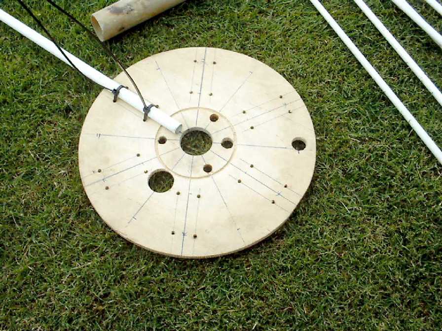
I took one of the timber end "cheeks" from an empty coax cable drum, drew lines from the centre at 60 degree intervals, and drilled two holes each side of these lines.
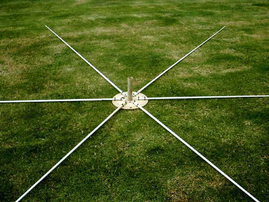
I took six glassfibre rods about 8ft long, and 1/2 ins O/D tapering to about 1/8th ins O/D, and tied them to the timber hub using TY Wraps as in the photos below...
14:30
I cut a driven element to the formula 468/f (wrong formula as it turned out...) and attached it to the glass fibre arms, followed by the reflector cut 3 % larger..
15:30
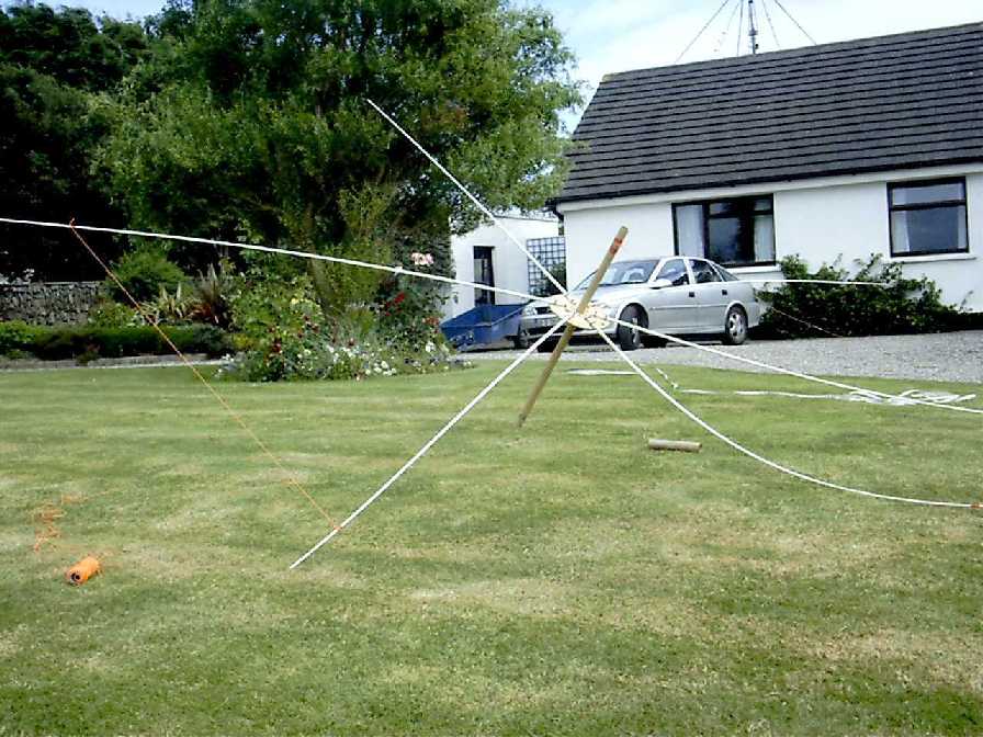
Elements attached...HEX airborne at about 5ft high....!! Resonance all wrong...Swift recalculations...New formula is 520/f...Made the reflector 4% larger
Aha!!! That's better.....Resonant in the band..f/b could be much better...only 3 S points...We'll get that right soon.. HEX at 15ft high...Quad at 35ft high..HEX about 1 S point down on the quad....HMmmmmm...That's not bad...Looks as if this could be what I need on 40 and 30M..
16:30
If you guys n' gals are NOT homebrewers (tut tut..! Shame on you) you may be interested/relieved to know that these antennae are produced commercially by Traffie Technology There's lots of info and pics there of course. I have commented to a number of commercial HEX-BEAM users that they appeared to me to be a bit expensive. ALL assured me that they are very happy with the product, and that they are built to an extremely high standard..
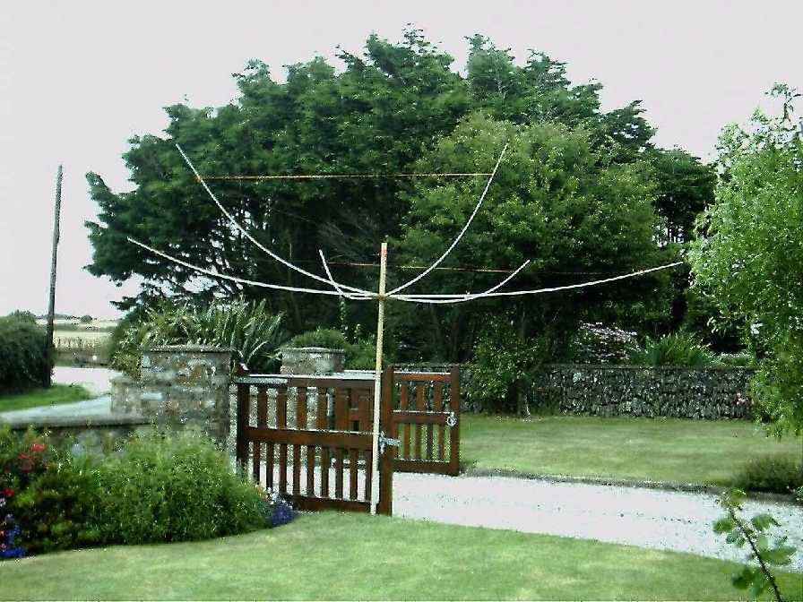
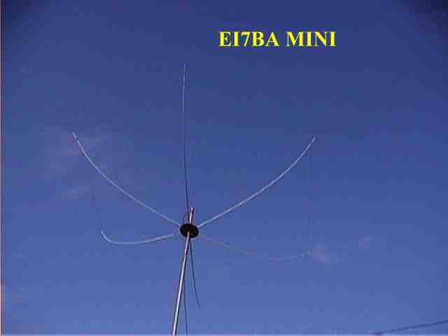
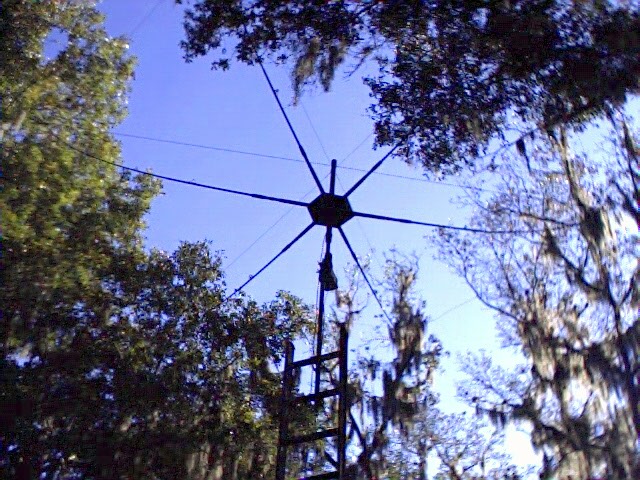
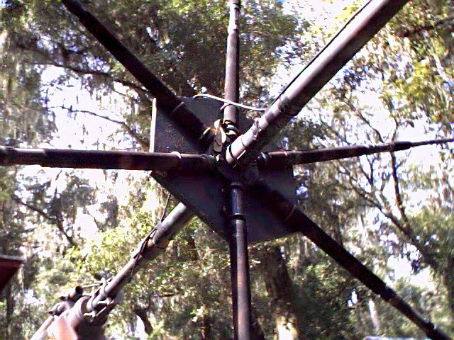
Here's a couple pics of Bill W5ONX's homebrew HEX... I have worked him on it, and it works a treat. You can probably catch him on 17m..
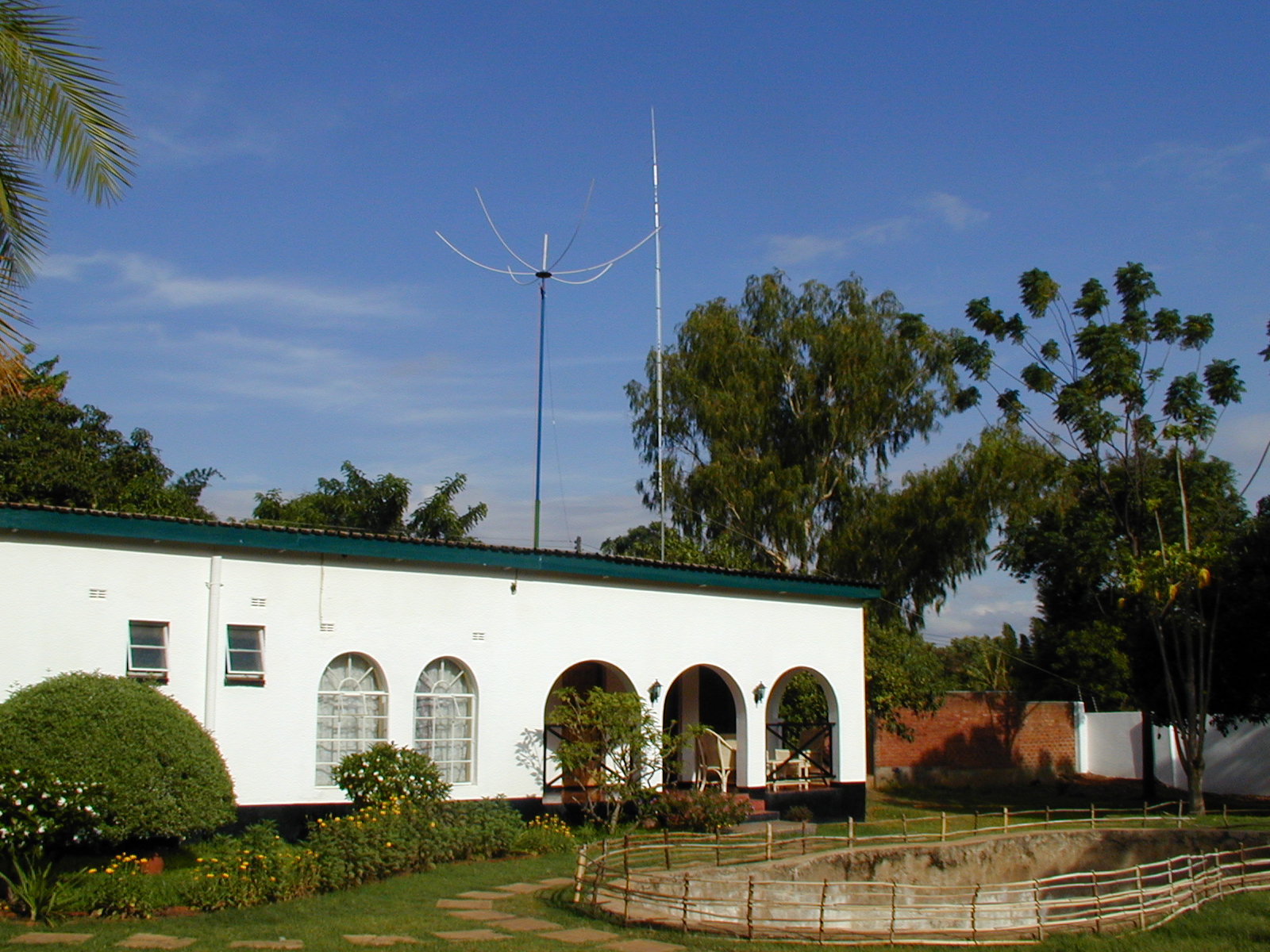
And this is Brian 7Q7BP and Janet 7Q7YL's fine HEX atop their homebrew tower..
What a beautiful QTH...!
PLEASE NOTE...
The above antenna was an experiment... It confirmed for me the fact that this is an antenna that works extremely well, in spite of the fact that it is really small and tidy.... HOWEVER...! I am NOT an expert on the Hexagonal Beam. If you need more information, you should join the Hex-beam afficionados at http://groups.yahoo.com/group/hex-beam/ .. There you will find the real experts VK2DPD, DL7IO etc, etc... Many of these guys have homebrewed mono and multiband HEXs, and they now have uncovered pretty well all of the secrets..
Not all are homebrewers of course..Many of the subscribers are satisfied users of the commercial product from Mike Traffie at Traffie Technology
> I want to be sure that I have the formula correct 520/f is the driven
> element formula. The Reflector is then made 4% larger than this. Is
> that correct?Nope.. As I stated above , my formula was "off the mark".... The guys on the HEX reflector all agree the following...Driven Element = 6180/Freq
Reflector = 6262/Freq
Tip Space (Driven Element) = 102/FreqTip Space (Reflector) = 65/Freq
Overall Tip Space = 145/Freq
Answers in inches...(A pic to explain the Tip spacing formulae.. )

>If this is so, then won't the reflector be a bit higher
> than the driven element?No.. The elements for each band will be at the same height, but each band will be at a slightly different height to the others bands.
> I take it the lower frequency bands are mounted higher up on the center
> post. Is there a critical distance by which the bands are separated in
> height along the center post?This will depend on how much "bend" you have on the spreaders.. The bend
depends on how stiff the spreaders are. There is a bend on the spreaders so
that they will pull on the elements to keep them taut.. The stiffer the
arms, the less bend you need. (and the shorter the centre pole..)>Or is it just by where they fall along
> the bend of the arms?Just by where they fall along the bend of the arms ...
> Is there much interaction between the wires of the band you are using,
> versus the unused bands? Does this have to be taken into account when
> designing multi band antennas?As in ANY multiband antenna, there is interaction between harmonically related bands (e.g 20 and 10m, or 40 and 15m etc) and also when the bands are very close to each other in frequency. (e.g 10 and 12m). This can be greatly reduced by proper design. Using a choke balun is a good start..
> How does one calculate the length of the spreaders?Here's a quick example...say 20m..The above formula makes the driven element 36ft 3ins long (14.2mHz). divide
that by 4 to give you the length of a side on the equilateral triangles,
which equals 9ft 3/4ins .That makes the "wingspan" 18ft 1 1/2 inches.>Is there a proper
> amount of bowing?
The arms would have to be a bit longer than the radius, so as to get a
"bow" on them, This bending of the arms, is what keeps the elements taut.
The stiffer the arms, the less "bow" you need.. For 20m I'd make the arms
about 10ft long..
The tip spacing is critical as regards f/b ratio.. I've attached a pic to
explain the formulae..
> Seems like a fun project.Yep...Like most antenna projects it can also be confusing..frustrating..dangerous...exhilerating...educational and GREAT FUN..!