To return to the this point, simply use your browser's "Back" button.
Baluns
Index
| Balun Misconceptions | |
| Proper Balun Design | |
| Engineering and Building Baluns | |
| Retrofit Balunstm | |
| RemoteBaluntm | |
| Feedline Isolation | |
| The Effect of a Balun's Lead Length | |
| Phase Delay Through Baluns | |
| Power Rating | |
| Balun Core Saturation | |
| Installing Baluns | |
| Weatherproofing | |
| RFI Applications | |
|
To return to the this point, simply use your browser's "Back" button. |
|
The RADIO WORKS introduced a full line of precision, 'Current-type©' baluns beginning in 1986. We were actually producing 'Current-type©' baluns, in 1984, but it was not until 1986 that they became generally available to the public. They were instantly popular because 'Current-type©,' baluns avoid the bad habits that conventional 'Voltage-type' baluns exhibit. 'Voltage-type' baluns produce equal and opposite voltages at the balun's balanced port. Since low impedance antennas are current fed, a balun that produces equal and opposite currents at its output over a wide range of load impedances is desirable. There is little to be gained by forcing the voltages of the two antenna halves, whether the antenna is balanced or not, to be equal and opposite compared with the cold side of the balun input. The antenna field is proportional to the currents in the elements, not the voltages at the feed point. Current-type baluns are not a new idea. They have been used in TV receivers for many, many years. TV tuners require a very wide bandwidth balun that will work with a severely mismatched antenna, like a TV's so-called 'rabbit ears' antenna. The Current-type balun was the best choice for that application. Unfortunately, when baluns were first popularized for use with wire antennas, a voltage-type design was chosen. Other balun makers just followed along. It was years before the first true, Current-type baluns appeared on the market. Of course, times change and today you can find entire books devoted to Current-type baluns. The Radio Works was the first to offer you a full line of Current-type baluns for every application. (This text was taken from the RADIO WORKS' Reference Catalog, copyright 1992, page 11.)
A balun really has only two jobs.
A properly engineered balun will include these design points:
<< 1/4 wave, the shorter the better 4 High power components- High voltage wire & insulation to withstand high power or a mismatch. 5.Large wire gauge reduces I2R losses. 6.Large cores - prevents saturation and provide the necessary high inductive reactance values on the low bands. 7.Mechanical considerations: Weather- proofing, rustproof hardware and a strong case to withstand loads. To insure long life, each RADIO WORKS balun is filled with a potting compound. In some models, this is an expansive foam, while in others, a solid plastic potting compound is used. Balun cases are high quality, heavy-wall, PVC. Eye-bolts, if they are used, are made of stainless- steel. Wires from the internal windings of the B1, B4, B75, Y1, and RemoteBaluns are brought directly outside the case for connection to the antenna. This eliminates any chance of an unreliable connection. In most models, the all-important wire used to make the internal transmission line(s) is insulated with Teflon® or similar materials. Top of the line models use silver-plated wire and Teflon® insulation for maximum power handling and minimum power loss. All 1:1 and some 4:1 models are Current-type© designs. Current-type© baluns are extraordinarily saturation resistant and provide superior reactance characteristics. Signal distortion and RFI, due to core overload is practically eliminated. Current-type© baluns are very forgiving when feeding antennas that do not provide an ideal load. Installing aY1-5K, 4K-LI or T-4 can substantially improve antenna performance by providing the antenna with balanced current and excellent feedline isolation. Adding a Y1-5K retrofit Current-balun©, a 4K-LI or T-4 to any antenna can significantly reduce feedline radiation, and dramatically decrease RFI and TVI. Beam antennas benefit from improved balanced drive and superior feedline isolation. An improved radiation pattern is the result. Also, receiver noise may be reduced by eliminating signal pickup by the feedline . You can have the convenience of coaxial cable combined with the flexibility of open wire. The RemoteBaluntm is a special, saturation resistant, Current-Type© balun capable of handling the legal power limit with loads of moderately high impedance. Unlike other baluns, the RemoteBalun is designed specifically for antennas fed with open- wire, ladder line or twin-lead. The balun is located outside where it belongs. A short length of very low loss coaxial cable connects your transmatch to the RemoteBalun. This eliminates the complication of routing balanced feeders into the radio room. RFI ApplicationsCurrent-type(c) baluns are especially effective in reducing RF current on outer surface of a coaxial cable's shield. This type balun has several exceptional features that are not present in other balun designs. For example, in RFI reduction, the most important factors are very high load isolation over a wide bandwidth, extremely low loss characteristics, and wide, low SWR bandwidth. See the section on RFI control devices in the General Catalog for further detail. |
 |
|
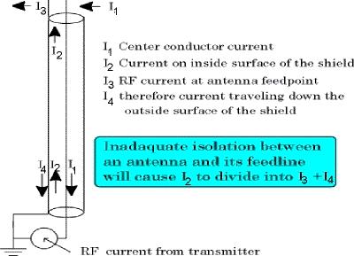
In this discussion there are four different RF currents flowing on or within a coaxial cable. There is an I1 current flowing on the center conductor of the cable. Due to the skin-effect, there are two currents flowing on the cable's braided second conductor (its shield) which surrounds the inner conductor. On the inner surface of the braid, there is the I2 current. At the antenna end of the coax I2 divides into I3 and I4. Without a device to isolate the antenna from the feed line, the outer surface of the coax's shield is part of the antenna, thus the division in current. I3 is radiated by the antenna and I4 flows along the coax. On its way back down the coax, some I4 current is radiated, some is conducted back to the transmitter and on to station's ground system, house wiring, etc. |
|
A balun or Line Isolator substantially reduces I4 current. It has little or no effect on I1 and I 2currents. With I4 reduced to nearly zero, I2 » I3. That means that nearly all of the I2 current is radiated by the antenna, and none by the feed line. The antenna pattern improves and most of the RF current flowing down the outer surface of the coax's shield is eliminated. The problem is to properly isolate the antenna from the transmission line. A current balun is the perfect device for the task, since we are working with equal RF currents at the feedpoint. Any of the RADIO WORKS' current-type baluns are perfect in this application. They all have excellent output balance and unmatched isolation factors. Line IsolatorsTM are designed to work with both balanced and unbalanced loads, but they are at their best when working with unbalanced loads. Although a well designed current balun will eliminate I4 current, there will be an induced current, call it I4i (subscript "i" for induced) flowing along the outside of the coax's shield. This current is the result of the coax being the radiation field of the antennas. Obviously, since the coax conducts the RF energy to the antenna it is not possible to physically isolate the coax from the effects of the antenna's radiation field. Consequently, it is advisable to install a Line Isolator at the transmitter end of the coax to eliminate the ground path for the RF current induced by the antenna's radiation field. The length of the coax will have some influence on the RF induced onto the coax. You may notice that when you add a RADIO WORKS Current-type© balun to an existing antenna system, a dipole for example, the resonant frequency will move upwards a bit. When this happens, you know that the coax was acting as part of the antenna making it appear longer. The current balun isolated the coax from the antenna and the antenna is now operating closer to its formula frequency. Experiencing this effect, leaves little doubt that the balun was needed and is useful even with dipoles and similar, simple antennas. A flat SWR curve Current or Voltage Baluns? Most commercial baluns are voltage-types. As such, their performance is poor unless they are operated under ideal conditions. Even under the best of conditions, a perfect match, low power, etc. insufficient winding inductance and poorly designed transmission lines sacrifice efficiency and reduce bandwidth. The B4-2KX balun is an excellent example. It is a high quality, high power, twin transformer 4:1 balun. Two special ferrite toroids to help manage reactance and provide the inductance values nec essary in a 4:1 balun. The output impedance of the B4-2KX balun is 200 ohms. The inductive reactance of the internal windings must be at least 1000 ohms to effectively isolate your antenna from its transmission line. I have measured other commercial baluns where this value is only 240 ohms. This is a uselessly low value. Here is another example: The transmission lines in many 1:1 and 4:1 baluns is #14 enamel covered wire. The impedance of such a transmission line (two wires in parallel) is generally between 20 and 25 ohms. This value is totally inappropriate. It should be 50 ohms if the balun is to be used with 50 ohm coax. Otherwise, bandwidth will suffer and unwanted reactance can be introduced into your antenna system. We use very carefully designed transmission lines. We use #14 wire and the spacing between the wires determines the line's impedance. This is carefully controlled to provide maximum bandwidth, power handling, and minimum effect on antenna tuning. Look at the diagram above. Here, our B4-2KX is compared with the most popular 4:1 balun on the market. Notice the narrow, low SWR bandwidth of the competitors balun and compare it with the nearly perfect curve of the B4-2KX. Achieving this kind of result is difficult. It is difficult to produce the necessary inductance reactance on the low bands without introducing unacceptable capacitive reactance and leakage on the upper bands. Broadband performance is possible only through the correct application of both selected ferrites and properly designed transmission lines and L/C compensation networks. The mechanical construction of the balun also influences the final characteristics of any balun. Wire Lead Length and Tuning EffectsThe length of a balun's output lead can have an effect on the tuning of your antenna. These leads are part of the antenna and in some applications, can make antenna resonance drop in frequency by a small amount. The effect is greatest on 10 meters where the length of the balun output leads are the longest in terms of antenna length. On 80 meters there should be no noticeable effect. The Yagi Baluns have precisely measures leads. Occasionally you should take the extra lead length into account. Most of the time, an inch or two, will make little difference if Gamma or Beta matching schemes are used. The same can be said of most simple antennas. Phase DelayAll RADIO WORKS Line Isolatorstm have a specified delay time through Line Isolators. This value is unimportant unless the Line Isolators are used in matching sections, phasing line or similar applications. If the length of the transmission line or matching stub is critical, use the phase delay figure in the specifications to compensate for the addition of the Line IsolatorsTM to the system. For example, the C75-4K Line IsolatorsTM has a phase delay at 3.5 MHz of 2.90. Double the frequency and you double the delay. To find the delay at a specific frequency, use the formula at right. Sometimes the phase delay is important. Here is a simple example. Suppose you are building a full-wave loop antenna for 7.2 MHZ. You plan to use a 75 ohm quarter- wave matching stub (commonly known as a Q-section) to match the loops' 120 ohm impedance to 50 ohms. The formula for the matching stub is A quarter-wave stub for 7.2 MHZ using a solid dielectric coax with a velocity factor .66 is To compensate for the installation of a C75-4K Line IsolatorsTM , the stub will have to be shortened slightly long due to the phase delay of the Line Isolatorstm. The phase delay of a C75-4K is 5.960 @ 7.2 MHz. The calculated quarter-wave stub length @ 7.2 MHz is 22.5'. We should shorten the coax part of the matching stub by 5.960 if we want optimum results. To find the length, follow this formula. Shorten the coaxial stub by 1.45 feet (1.5' when rounded off) Subtracting 1.5 feet from the 22.5 foot stub yields 21.0 feet. Add the Line IsolatorsTM and the stub is again 900. Phase delay exists in all baluns and similar devices. We give you the numbers to take advantage of it. Power RatingAll products made by the RADIO WORKS will handle the legal power limit, unless it is specifically designed for low power or receiving applications. Since The RADIO WORKS advocates adherence to the legal power limit, I do not like to rate components above that level. However, since 2:1 and 3:1 safety factors are often desirable, the RADIO WORKS does build heavy duty components. Rated power assumes an SWR of less than 2:1 unless otherwise noted. The rated frequency is 3.5 MHz. Duty-cycle is CW or SSB with normal processing. High duty cycle modes, like RTTY, may over stress a balun and require improvement in load matching, lowering the power, or switching to a higher rated balun. SaturationWhen a ferrite core balun saturates, you will notice an upward drift in SWR long before the balun fails. Core saturation can be caused by too great a mismatch at the load (antenna) or by running two much power or a combination of both. If you see an upward movement in SWR, locate the problem immediately. If you must stay on the air, lower power until SWR drift ceases. In new installations, tune the antenna system for minimum SWR. Apply a few hundred watts of power on each band the system covers. Monitor the SWR with power applied. Do not exceed the time limits of your amplifier. Increase power gradually until maximum power output is achieved. Watch the SWR or reflected power meter closely. If the SWR drifts upward, locate the problem before continuing operation. RemoteBalunstmRemoteBaluns are a special case. They operate under the most difficult conditions. The checkout procedure for the RemoteBalunsTM is the same as in the previous paragraph. If you notice the SWR drift on one or two bands, this usually means that the load impedance is too high or too low for efficient balun operation. Changing the length of the balanced feeders (ladder line) by a few feet or ideally, 1/4 wavelength, will often remedy the situation and permit full power operation. InstallationWhile there are no special mounting requirements, I do suggest strain relief for long unsupported transmission lines. Use standoffs for your coaxial cable. This can improve the front-to back and front-to-side ratios of your beam antenna. It doesn't make sense to put up a good beam and then let the feed line radiate (because of a poor balun). It also doesn't do your antenna system any good to couple your coaxial cable to a large vertical antenna (like your tower). Taping your coaxial cable to a tower leg creates a large capacitor which effec tively couples your beam and vertical antenna (tower) together. Use stand-offs to hold the coaxial cable away from the tower leg. This procedure in combination with a RADIO WORKS balun can dramatically improve the front-to-side ratio of some beams. There are no special mounting requirements. The unit may be supported by the eye-bolt or strapped to the antenna's boom and secured with waterproof tape or quality hose-clamps. Lightning ProtectionSome balun manufacturers will tell you that their baluns have built in lightning protection. Those that do, use spark gaps which are absolutely useless. The high winding inductance of our baluns offers some protection, but for proper protection, use devices intended specifically for "surge" protection. WeatherproofingEach RADIO WORKS balun is either potted in solid plastic or expansive foam. All critical components are completely protected even if water enters the balun's case. Moisture can enter the balun case only through the holes where the wires emanate. You can completely seal your balun by putting a small amount of CoaxSeal around wires leaving the case. Press the CoaxSeal firmly around the wire and against the case. Make sure the coax seal 'wets' (or sticks) to both the wire and the case. This will insure a weather tight seal. Always protect all coaxial connectors with CoaxSeal. Seal all electrical components and coaxial connectors exposed to the weather. Use CoaxSeal(r) to wrap any connector that is exposed to the weather. Generously wrap each connector and mold the layers together with your fingers to insure a solid, impenetrable seal. |